Neutron.
One forward pass.
Start with a rocket at rest. Calculate its forces, advance its state, then follow the payload to orbit and the booster home.
Follow one 8,000 kg payload to a 400 km orbit, with booster recovery. Every flight result comes from the same default run. Calculations use SI units; displayed kilometres are labelled.
This is a five-state planar translation model. Guidance reads the simulated state directly at each solver evaluation, and thrust force is applied immediately. Sensors, state estimation, attitude dynamics and actuator response are outside this model. The Python model computes the complete flight before playback begins.
The attached stack
Stage 1: launch to separation
Begin at rest on a spherical, nonrotating Earth. The model tracks motion in one flight plane, with a still atmosphere and ideal thrust pointing.
Start with five numbers
Symbols in this section
- Elapsed time and launch time; the reference run starts at zero. [s]
- Distance from Earth's centre and the fixed spherical Earth radius. [m]
- Signed angle from the launch radius, increasing in the chosen downrange direction. [rad]
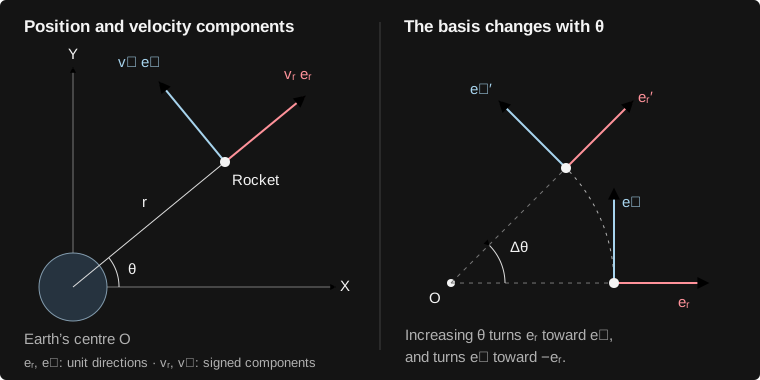
- Local unit directions: outward from Earth's centre and perpendicular to it toward increasing angle. [dimensionless]
- Signed velocity components along and ; positive means outward and downrange. [m/s]
- Current attached mass, launch mass, and carried upper assembly mass (upper dry structure, propellant and payload). [kg]
- Altitude above the model surface and signed downrange arc length on that surface; these are derived outputs. [m]
- Ordered five-state column vector, transpose, and launch-value subscript; its entries have different units. [mixed, by entry]
At time in seconds, the state is the five numbers carried from one calculation to the next. Subscript means liftoff: the rocket starts at rest with full thrust applied immediately.
is distance from Earth’s centre (m); is the angle travelled from the launch point (rad).
is outward velocity and is local tangential velocity, positive downrange (m/s); is the entire attached stack’s mass (kg).
The three terms are stage 1 dry mass, stage 1 propellant, and the carried assembly. That last 115,000 kg includes its structure, fuel and an 8,000 kg payload. These internal masses are model assumptions.
Carry forward: the current time and this five-number state.
Why these terms appear
Radius is measured from Earth's centre, not from the ground. Tangential velocity is the local arc rate at radius ; ground downrange instead uses the fixed surface radius . Consequently , not generally .
The two entries in each unit vector are components along fixed Cartesian axes in the flight plane. The first axis points from Earth's centre through the pad. The local directions rotate as changes, even though this Earth does not rotate. A velocity component may be negative; speed is a nonnegative magnitude.
The five states describe planar translation and attached mass. There is no attitude, angular rate, out-of-plane motion, pad hold-down, Earth rotation or launch-latitude model. At liftoff the engine force is already applied; engine startup is outside this calculation.
All worked numbers in this lesson use an 8,000 kg payload and 60,000 kg recovery reserve. The quoted 480,000 kg is the resulting reference-case mass; changing the payload in the executable runner changes the actual initial mass.
Associated code · 3 source excerpts
Copied directly from the implementation used by this site. Excerpts show the surrounding logic; run the complete downloaded notebook for dependencies and execution order.
MU = 3.986004418e14              # Earth gravitational parameter [m^3/s^2]
EARTH_RADIUS = 6_378_137.0       # spherical Earth radius [m]
G0 = 9.80665                    # Isp reference gravity [m/s^2]
@dataclass(frozen=True)
class Vehicle:
    """Published geometry/thrust; explicitly assumed internal mass and Isp."""
    height_m: float = 43.0
    diameter_m: float = 7.0
    published_liftoff_mass_kg: float = 480_000.0
    advertised_leo_payload_kg: float = 13_000.0
    booster_engines: int = 9
    booster_thrust_n: float = 1_450_000.0 * 4.4482216152605
    upper_thrust_n: float = 890_000.0
    booster_dry_kg: float = 30_000.0   # assumption, includes captive fairing
    booster_propellant_kg: float = 335_000.0
    booster_isp_s: float = 330.0
    upper_dry_kg: float = 5_000.0
    upper_propellant_kg: float = 102_000.0
    upper_isp_s: float = 365.0
    drag_coefficient: float = 0.35
    area = math.pi * vehicle.diameter_m**2 / 4
    upper_wet = vehicle.upper_dry_kg + vehicle.upper_propellant_kg * upper_propellant_scale + payload_kg
    initial_mass = vehicle.booster_dry_kg + vehicle.booster_propellant_kg + upper_wet
    initial = np.array([EARTH_RADIUS, 0.0, 0.0, 0.0, initial_mass])
Steps 2–4 use the same trial time and state: thrust, drag, then all five rates.
Point the thrust
Symbols in this section
- Commanded thrust-direction angle above the local positive horizontal, in degrees and in radians respectively. [°, rad]
- Times and degree-valued pitches at the two knots bracketing the current time; a and b label endpoints. [s; °]
- Magnitude of the total nine-engine thrust, held constant during the powered ascent. [N]
- Signed thrust-force components in the local outward and positive downrange directions; gravity and drag are separate. [N]
- Flight-path angle of velocity above the local horizontal; defined only when speed is nonzero. [rad]
The pitch angle is measured above the local horizontal. The model linearly interpolates this assumed schedule and holds the endpoint pitch outside its time range:
| Time (s) | Pitch (°) |
|---|---|
| 0 | 90 |
| 12 | 90 |
| 35 | 82 |
| 70 | 67 |
| 115 | 52 |
| 160 | 40 |
are thrust components (N). The total thrust stays at 6.4499 MN during ascent. The implementation applies the commanded direction instantly.
Why these terms appear
These endpoint checks explain the sine on the radial component and cosine on the tangential component. The angle is measured from the horizontal, so the radial force is opposite the angle in the component triangle. Degree labels here describe the directions; trigonometric evaluation in Python uses radians.
Pointing the thrust at does not instantly turn the velocity to the same angle. Forces change velocity over time, so the flight-path angle generally differs from . This model commands thrust direction directly; it does not integrate body attitude, gimbal motion or angle-of-attack aerodynamics.
The thrust conversion uses ; lbf means pound-force, not mass. The total is not multiplied by nine again. Constant thrust and specific impulse omit throttle, startup and ambient-pressure variation.
The pitch knots are an assumed open-loop schedule. Linear interpolation makes pitch continuous at each knot, while its slope can change there. Pitch is held at 40° after the last knot until the mass event stops the powered phase.
Associated code · 1 source excerpt
Copied directly from the implementation used by this site. Excerpts show the surrounding logic; run the complete downloaded notebook for dependencies and execution order.
def ascent_guidance(time, state, vehicle):
    """An assumed pitch program; angles measured above local horizontal."""
    pitch = np.interp(time, [0, 12, 35, 70, 115, 160], [90, 90, 82, 67, 52, 40])
    beta = math.radians(pitch)
    return vehicle.booster_thrust_n * np.array([math.sin(beta), math.cos(beta)])
Find the air, then the drag
Symbols in this section
- Altitude, atmospheric density at that altitude, and reference sea-level density (1.225 kg/m³). [m; kg/m³]
- Density scale height: 8,500 m, the altitude increase that reduces density by a factor of e above the surface. [m]
- Speed relative to the still atmosphere; the magnitude of the two signed velocity components. [m/s]
- Vehicle diameter (7 m), circular reference area, and constant assumed drag coefficient (0.35). [m; m²; dimensionless]
- Dynamic pressure and nonnegative drag-force magnitude; pressure becomes force only after multiplying by coefficient and area. [Pa; N]
- Signed components of the drag force, opposite the respective components of velocity. [N]
is altitude (m), is Earth’s radius, and is speed through the still atmosphere (m/s).
is air density (kg/m³). The assumed atmosphere has sea-level density 1.225 kg/m³ and an 8,500 m scale height.
are drag components (N). The assumed drag coefficient is . The reference area is = 38.48 m². Negative signs make drag oppose velocity.
Why these terms appear
The density exponent is dimensionless because altitude and scale height use the same units. The max operation caps density at its sea-level value for a trial state below the surface; the separate impact event terminates physical flight at the surface.
Divide velocity by speed to obtain its direction, then reverse it and multiply by drag magnitude. Cancelling one speed factor gives the implementation's expression, which also evaluates safely to zero at launch without division by zero. During descent the radial velocity is negative, so radial drag points outward.
Dimensional check: has units kg/(m·s²) = Pa; multiplying by gives kg·m/s² = N. is a pressure, not an acceleration. The solver-component index in step 5 is unrelated to dynamic pressure.
This is a one-layer density law with constant drag coefficient and frontal area. It omits lift, winds, atmospheric rotation, Mach-dependent aerodynamics and heating. Fairing opening later does not alter this area or coefficient.
Associated code · 2 source excerpts
Copied directly from the implementation used by this site. Excerpts show the surrounding logic; run the complete downloaded notebook for dependencies and execution order.
def atmosphere(altitude_m):
    """One-layer density model, not a weather or aerothermal model."""
    return 1.225 * math.exp(-max(0.0, altitude_m) / 8500.0)
def drag_force(state, area_m2, cd):
    """Components in the local outward/tangential frame; still atmosphere."""
    radius, _, vr, vt, _ = state
    speed = math.hypot(vr, vt)
    scale = -0.5 * atmosphere(radius - EARTH_RADIUS) * cd * area_m2 * speed
    return np.array([scale * vr, scale * vt])
Calculate all five rates of change
Symbols in this section
- A time derivative: rate of change per second in the fixed Earth-centred frame, with local velocity components expressed on the rotating basis. [quantity/s]
- The right-hand-side function returning all five state rates from the same trial time and state. [mixed, by entry]
- Physical acceleration vector components along the current local radial and tangential directions, obtained from net force per unit mass. [m/s²]
- Rates of the stored velocity components; changing local directions makes these differ from physical acceleration components. [m/s²]
- Earth's gravitational parameter and local inward gravity magnitude . [m³/s²; m/s²]
- Specific impulse (330 s), fixed reference gravity (9.80665 m/s²), and effective exhaust speed, their product. [s; m/s²; m/s]
- Signed specific angular momentum about Earth's centre; specific means per unit mass. [m²/s]
A dot means “change per second.” Insert the thrust and drag just computed into the following equations. Together they form , the function evaluated by the solver.
Velocity advances the position and the angle around Earth.
The rate of the outward velocity component combines the coordinate term, gravity and radial force per unit mass. Earth’s gravitational parameter is m³/s².
This is the rate of the tangential velocity component, not just tangential force divided by mass. The term accounts for the turning local basis. The derivation below shows exactly where its sign and factors come from.
is the assumed specific impulse; is standard gravity. Their product is effective exhaust speed. The thrust magnitude equals during ascent and zero during coasts. Thrust already accounts for exhaust momentum.
Carry forward: five derivatives, all evaluated from the same state. No state component has been advanced yet.
Scroll the diagram sideways to inspect both ends.
Why these terms appear
Differentiate the sine/cosine unit vectors from step 1. Increasing turns the outward direction toward the tangent and turns the tangent toward the inward direction. The chain rule contributes .
Apply the product rule to both velocity components and their directions. The cross terms appear because the directions themselves change; differentiating the two stored numbers alone would miss them.
Newton's law applies to physical acceleration. Gravity points entirely inward, so it contributes to only. Solve these identities for the stored component rates to obtain the two velocity equations in the ODE.
Tangential acceleration is not simply . The force-driven tangential acceleration is ; the extra negative term belongs to the derivative of the tangential velocity component. It includes division by radius and is required even on a nonrotating Earth. It is not an extra aerodynamic or engine force.
An independent check: with no tangential force (for example gravity-only flight with drag omitted), and stays constant. As an outward-moving vehicle's radius grows, its positive tangential component must fall. During inward motion it grows. Omitting the cross term would violate this angular-momentum identity.
This is a chosen local-state example, not a sampled flight result. The units are . With m/s at the same radius, tangential speed and force, the correction changes sign and m/s². With either velocity component zero, this correction is zero.
Specific impulse is thrust divided by propellant weight flow, so multiplying it by the fixed reference gravity gives effective exhaust speed. Dividing thrust by that speed gives a positive propellant consumption rate; the vehicle mass derivative is its negative. Use here, not altitude-dependent .
Evaluation order follows dependencies, not a sequence of physical changes: read one complete trial state and its time; derive altitude and speed; evaluate density, thrust direction and drag; divide the net forces by that same mass; then form all five rates. The ascent pitch schedule depends only on time, so its evaluation can occur before or after the atmosphere calculation. None of these calculations overwrites the trial state.
The radial term has the same geometric origin: . In a circular gravity-only trajectory, and , so even while physical acceleration is inward. Zero radial velocity derivative does not mean zero acceleration vector.
Python's rhs names radial and tangential for the thrust-plus-drag acceleration components before adding gravity and the geometric terms. The returned entries [2] and [3] are the complete radial and tangential velocity derivatives. Tiny nonzero horizontal values at a nominal 90° pitch can arise from floating-point cosine evaluation.
Associated code · 1 source excerpt
Copied directly from the implementation used by this site. Excerpts show the surrounding logic; run the complete downloaded notebook for dependencies and execution order.
def rhs(time, state, guidance, area_m2, cd, isp_s):
    """Polar Newton equations; state = [r, theta, v_r, v_t, mass].

    Pointing is ideal: guidance commands force directly, not attitude/torque.
    The changing mass appears in F/m and dm/dt; thrust includes exhaust momentum.
    """
    radius, _, vr, vt, mass = state
    force = guidance(time, state)
    radial, tangential = (force + drag_force(state, area_m2, cd)) / mass
    return [vr, vt / radius,
            vt * vt / radius - MU / radius**2 + radial,
            -vr * vt / radius + tangential,
            -np.linalg.norm(force) / (isp_s * G0)]
Advance the state, then repeat
Symbols in this section
- Accepted-step index; trial-stage index; earlier-stage index; state-component index from 1 to 5. None is time itself. [dimensionless indices]
- Time of the current accepted state, proposed time increment, and current accepted five-state vector. [s; s; state units]
- Five-rate vector evaluated at trial stage i; its components have each state's units divided by seconds. [state units/s]
- Fixed method coefficients: trial-state weights, time fractions, fifth-order weights and embedded fourth-order weights. [dimensionless]
- Proposed fifth-order state and difference between the embedded fifth- and fourth-order estimates; (5) means method order, not exponent. [state units]
- Component absolute tolerance, dimensionless relative tolerance (10⁻⁷), and combined error scale for that component. [state units; dimensionless; state units]
- One component of the estimated local error, and the root-mean-square of all five scaled errors. [state units; dimensionless]
- Dummy time variable inside an integral and the complete trial state passed to rate evaluation i. [s; state units]
- Equivalent web shorthand: is a trial state; is the fifth-order candidate. [state units]
The solver uses Dormand–Prince RK45. Within a trial step (s), it recalculates forces and derivatives at intermediate times and states, producing slopes .
- Read the trial snapshot all belong to the same solver trial.
- Calculate dependenciesCurrent radius and velocity give altitude, density and speed. Current time, state and phase determine the thrust command.
- Calculate forces, then ratesResolve thrust and drag. Divide forces by the current mass, add gravity and coordinate terms, and calculate mass flow. Collect without overwriting the state.
- Build the next trial togetherRK45 combines earlier slopes to construct all five components of its next trial state. Repeat the force calculation on that whole state.
- Accept, reject or stop at an eventAccept the complete state if the error test passes; otherwise retry from the previous accepted state. A terminal event ends the phase at its root, then the new phase uses that event state.
There is no physical “radius first, velocity second” update. Forces set acceleration; velocity sets position rate. These coupled rates evolve over the same time interval.
counts accepted steps; counts solver stages and earlier stages. are fixed RK45 coefficients; is a trial state.
are the fifth-order weights. A second set of weights gives a fourth-order estimate. If their scaled difference is small enough, accept and . Otherwise shrink the step and retry from .
RK45 coefficients and error control
The seven rows give the trial time fractions and the weights on earlier slopes. Blank entries are zero. The seventh row evaluates the derivative at the fifth-order candidate.
| cᵢ | aᵢ₁ | aᵢ₂ | aᵢ₃ | aᵢ₄ | aᵢ₅ | aᵢ₆ |
|---|---|---|---|---|---|---|
| 0 | — | |||||
| 1/5 | 1/5 | |||||
| 3/10 | 3/40 | 9/40 | ||||
| 4/5 | 44/45 | −56/15 | 32/9 | |||
| 8/9 | 19372/6561 | −25360/2187 | 64448/6561 | −212/729 | ||
| 1 | 9017/3168 | −355/33 | 46732/5247 | 49/176 | −5103/18656 | |
| 1 | 35/384 | 0 | 500/1113 | 125/192 | −2187/6784 | 11/84 |
The fifth-order weights are the last row’s six slope weights followed by zero. The fourth-order weights, in order, are 5179/57600, 0, 7571/16695, 393/640, −92097/339200, 187/2100 and 1/40.
Here selects one of the five state components. The absolute tolerances , in state order, are 0.001 m, 10⁻¹¹ rad, 10⁻⁵ m/s, 10⁻⁵ m/s and 0.0001 kg. SciPy adjusts the step using the error to the power −1/5, with safety and growth bounds; the maximum step is 2 s.
SciPy RK45 method reference. The model uses SciPy 1.17.0.
Repeat this force-to-state calculation while monitoring the cutoff condition below.
Why these terms appear
Start from the definition of a derivative: each state change is the integral of its rate over the same time interval. All five rates depend on the evolving state, so the equations are coupled. Position, velocity and mass evolve together; there is no physical rule that one must finish updating before another starts.
The actual RK45 ordering is between trial stages: build all five entries of a trial state from already available slopes, then read that complete trial state to compute all five new rates. Within a rate evaluation, compute the needed derived quantities and forces before the rates. Earlier-stage slopes are known inputs; intermediate trial states are not accepted flight states.
A teaching-only forward-Euler example makes the dependency rule visible: every right-hand side has the old index . The saved rates and are the complete expressions from step 4, evaluated at that same old state and time. Save all rates before writing any new component. Updating radius in place and then using that new radius with old velocities silently defines a different numerical method. The implemented RK45 uses multiple trial evaluations and weighted slopes, not these Euler updates.
Near launch, outward acceleration first creates velocity, and the time integral of that increasing velocity creates altitude. Euler using only the zero initial velocity would produce no altitude change on its first step. RK45 samples accelerated intermediate states, which is why its first accepted altitude is positive. This describes continuous causation, not permission to overwrite velocity before evaluating the other rates.
The embedded methods reuse rate evaluations to estimate local error. Scaling each component before combining them prevents metres, radians, metres per second and kilograms from being compared directly. SciPy may use the opposite sign for the difference; the squared norm and acceptance decision are identical.
The relative tolerance acts on the stored Earth-centred radius, not altitude. Thus a radius absolute tolerance of one millimetre does not imply one-millimetre altitude accuracy. This scale participates in an RMS acceptance test across all five states; it is not a guaranteed per-component or global error bound.
The coefficient table uses for earlier Runge–Kutta stages. The web error-control panel also uses to select a state component; that role is written in the download. In the error formulas, therefore mean exactly ; neither index denotes a physical variable.
The full loop is: accepted time and five-state vector → complete trial stage → derived altitude, speed and density plus commanded thrust → drag and net forces → all five rates → further trial stages → candidate state and error estimate → accept the whole vector or retry the whole step. Force evaluation uses a decreasing trial mass on later stages, so rising thrust acceleration is included without a separate mass-first update.
A rejected trial does not become a new flight state. RK45 retries from the same accepted state with a smaller time increment. Several trial force evaluations can therefore occur before one state is accepted; a function-evaluation count is not a count of accepted steps.
The 2 s maximum step is a ceiling, and the 2 s output interval is a separate display choice. The solver selects its own first and later steps. Dense output uses a quartic interpolating polynomial inside accepted RK45 steps; it supplies both display samples and states used by the event root search.
A small numerical error estimate cannot validate the physical assumptions. Check numerical convergence by tightening tolerances and maximum step and comparing event times and separation states. The download's automated checks also compare against the canonical simulator, analytic burn time and separation momentum.
Associated code · 1 source excerpt
Copied directly from the implementation used by this site. Excerpts show the surrounding logic; run the complete downloaded notebook for dependencies and execution order.
def integrate(state, start_s, end_s, guidance, area_m2, cd, isp_s,
              events=(), max_step_s=2.0, rtol=1e-7):
    """Integrate one continuous phase; restart after every discrete change."""
    solution = solve_ivp(
        lambda t, y: rhs(t, y, guidance, area_m2, cd, isp_s),
        (start_s, end_s), state, method="RK45", dense_output=True,
        events=events, max_step=max_step_s, rtol=rtol,
        atol=[1e-3, 1e-11, 1e-5, 1e-5, 1e-4])
    if not solution.success:
        raise RuntimeError(solution.message)
    return solution
Stop burning at the fuel reserve
Symbols in this section
- Booster dry mass plus retained recovery propellant, and the still-attached upper assembly mass. [kg]
- Total attached mass at which the ascent burn stops; retained propellant is still part of this mass. [kg]
- Event residual: current mass minus cutoff mass; g is the web shorthand for this same gate, not gravitational acceleration. [kg]
- Elapsed time of main engine cutoff, located at the downward zero crossing of the mass residual; the two symbols name the same time. [s]
Main engine cutoff (MECO) occurs when the stack reaches the carried assembly’s mass plus stage 1 dry mass and its unburned reserve.
is the cutoff threshold. The 60,000 kg reserve is a chosen model input.
is the event function. SciPy locates its zero crossing within the accepted step and ends powered integration at that time, . The arrow means a crossing from positive to negative; means the reverse.
The integration also stops on downward ground contact, or at 600 s if cutoff is never reached. Those paths do not proceed to a successful separation.
Why these terms appear
Integrate the constant mass derivative during the powered phase and solve for the crossing time. The 275,000 kg burned is initial mass minus cutoff mass; the 60,000 kg reserve is retained, so MECO is not fuel exhaustion. This analytic time works because thrust and specific impulse are constant.
The terminal event requests the decreasing crossing. A sign change between accepted states brackets a root; the solver refines its time using the continuous interpolated solution and returns that root state. The event need not coincide with a 2 s output sample, and the model does not wait for the next display frame.
Changing only payload adds the same mass to launch and cutoff, so the analytic burn time is unchanged at fixed thrust and reserve, even though the acceleration and trajectory change. Increasing the reserve reduces the mass burned and shortens the burn.
The ground residual is altitude in metres and the MECO residual is mass in kilograms; an event function needs a zero crossing, not common units with other events. Ground impact and the 600 s phase limit are failure paths, checked separately before the coast is started.
Associated code · 2 source excerpts
Copied directly from the implementation used by this site. Excerpts show the surrounding logic; run the complete downloaded notebook for dependencies and execution order.
def terminal_event(function, direction=-1):
    """SciPy locates a zero crossing between accepted RK45 steps."""
    function.terminal = True
    function.direction = direction
    return function
    coast = lambda t, y: np.zeros(2)
    reserve_mass = vehicle.booster_dry_kg + recovery_propellant_kg
    meco = terminal_event(lambda t, y: y[4] - upper_wet - reserve_mass)
    record("liftoff", 0, "stack", "Nine-engine ascent begins.")
    time, state, impacted, ascent_solution = phase("stack", "ascent", initial, 0, 600,
                                                  lambda t, y: ascent_guidance(t, y, vehicle), (meco,))
    ascent_complete = bool(ascent_solution.t_events[1].size) and not impacted
Coast for four seconds
Symbols in this section
- Main engine cutoff time and stage-separation time, four seconds later in the reference sequence; each pair is equivalent notation. [s]
- State immediately before and immediately after a change of phase; minus and plus indicate one-sided limits, not negative and positive times. [state units]
- Prescribed fairing-opening fraction, and a clamp that limits its argument z to the interval from zero to one. [dimensionless]
is separation time, written as in the branches below. Restart the same five equations from the cutoff state with zero thrust. Gravity and drag still change the velocities; mass remains 205,000 kg. Downward ground contact remains a terminal event.
The captive fairing opens during these four seconds. Its opening is a kinematic display model; it changes neither drag area nor mass in the equations.
Carry forward: the final attached-stack state, ready for an instantaneous mass split.
Why these terms appear
Substitute zero thrust into the same equations. Coast means no engine thrust; it does not mean constant velocity or zero acceleration. Gravity, drag and the conversion between physical acceleration and rotating velocity components still apply.
The four-second denominator gives a dimensionless fraction. It is prescribed mechanism progress, not an extra ODE state. The fairing stays attached, so opening does not remove mass.
At cutoff, position, velocity and mass stay continuous because no impulse or mass drop occurs. Their derivatives may jump when thrust turns off. The solver is restarted at this known change so a single integration phase does not straddle the thrust discontinuity.
At an event the ordering is explicit: locate and retain the common event time and state, select the next phase's thrust command, then evaluate fresh rates from that unchanged state under the new command. At separation in step 8, apply the mass partition and paired velocity impulse before any subsequent branch integration. Never reuse the old phase's force or rate vector after a mode change.
The animation is kinematic: it adds no actuator forces, torques, drag-area change, contact or structural dynamics. Separation is attempted only after the full four-second coast without ground contact.
Associated code · 2 source excerpts
Copied directly from the implementation used by this site. Excerpts show the surrounding logic; run the complete downloaded notebook for dependencies and execution order.
    if ascent_complete:
        record("meco", time, "stack", "Main engine cutoff preserves the requested recovery reserve.",
               recovery_propellant_kg=float(recovery_propellant_kg))
        record("fairing_opening", time, "stack", "Captive fairing opens over four seconds (kinematic mechanism).")
        time, state, impacted, _ = phase("stack", "fairing_opening", state, time, time + 4, coast)
    def fairing_fraction(time, body):
        opening = next((e["time_s"] for e in events if e["name"] == "fairing_opening"), None)
        if opening is None or body not in ("stack", "booster"):
            return 0.0
        if separation_time is None or time <= separation_time:
            return float(np.clip((time - opening) / 4, 0, 1))
        return float(np.clip(1 - (time - separation_time) / 4, 0, 1))
Separate with momentum conserved
Symbols in this section
- Booster subscript, upper-assembly subscript, and the common attached state immediately before separation. [labels]
- Mass before separation and the two positive body masses after it; their sum is unchanged. [kg]
- Prescribed relative outward separation speed (0.5 m/s); this is shared between the bodies, not applied in full to each. [m/s]
- Magnitude of the instantaneous internal radial impulse: positive outward on the upper assembly, equally negative on the booster. [N·s = kg·m/s]
- Increase in the pair's translational kinetic energy due to the prescribed separation impulse. [J (joules)]
Split the final mass into the booster and the released assembly . The fairing stays with stage 1.
The assumed separation speed is the relative outward velocity between the two bodies. Superscript means just before separation; means just after.
Both bodies inherit the same . The impulses change only their radial velocities. There is no artificial position jump.
Why these terms appear
Start with equal and opposite impulses. Divide each impulse by that body's mass to obtain its velocity change, then subtract the two velocities to impose the requested relative speed. Over this ideal instantaneous split, the accumulated impulse from continuous external forces is neglected.
For 90,000 kg of booster and 115,000 kg of upper assembly, the lighter booster receives the larger speed change. Their difference is 0.5 m/s and their mass-weighted sum is zero, giving the momentum-preserving update above. These are increments, not the final radial velocities.
Momentum is conserved by the internal impulse, but translational kinetic energy increases. The prescribed impulse implicitly supplies separation energy; this model does not solve a spring, pneumatic system or contact mechanism. Energy conservation of the two bodies' translation alone is therefore not the intended separation check.
Both point masses initially occupy the common pre-separation position. The radial impulse changes their radial velocities immediately; position does not jump. No tangential impulse is applied, so both tangential velocities retain the common value.
There is no mass jettison at this split: the original attached mass is partitioned between two bodies. The captive fairing belongs to booster dry mass. The stage-one calculation ends with two initial separated states, each ready for its own subsequent propagation.
Associated code · 1 source excerpt
Copied directly from the implementation used by this site. Excerpts show the surrounding logic; run the complete downloaded notebook for dependencies and execution order.
def separate(state, booster_mass_kg, relative_speed_m_s=0.5):
    """Split mass with equal/opposite impulses: conserve linear momentum.

    Both bodies start at the same position. Geometry and contact are not modeled.
    The reusable fairing stays within booster dry mass.
    """
    booster, upper = state.copy(), state.copy()
    upper[4] = state[4] - booster_mass_kg
    booster[4] = booster_mass_kg
    booster[2] -= relative_speed_m_s * upper[4] / state[4]
    upper[2] += relative_speed_m_s * booster[4] / state[4]
    return booster, upper
The state we just propagated
Computed by the Python model. Display altitude is and ground distance is .
Scroll the table sideways for altitude, distance and mass.
| State | Time (s) | Altitude (km) | Downrange (km) | Mass (kg) |
|---|---|---|---|---|
| Launch | 0.000 | 0.000 | 0.000 | 480,000 |
| Engine cutoff | 137.979 | 56.588 | 40.314 | 205,000 |
| Before separation | 141.979 | 60.581 | 44.612 | 205,000 |
One separation. Two trajectories.
Separation creates two independent initial-value problems at the same mission time. Each branch now carries its own five-number state; is the mass of that body. Throughout these sections, means altitude and means specific angular momentum; they are different quantities. Both reuse the atmosphere, drag, ODE and adaptive RK45 loop already established above. Within each solver evaluation, every command and derivative comes from the same trial state: guidance reads it, force limits bound the command, and the ODE returns all five derivatives together. RK45 then constructs its next trial or accepted state. These equations describe dependencies, not sequential in-place updates of radius followed by velocity followed by mass. Phase-specific force commands, reference areas, propellant parameters and event gates use that same ODE. Read either branch forward from separation; the booster lands while the upper stage is still flying.
Upper-stage branch
Upper stage → payload orbit
Carry the upper state forward through clearance, powered insertion, apogee coast, circularization, deployment and one real unpowered orbit.
Coast clear of the booster
Symbols in this section
- Mission elapsed time, stage-separation time, and upper-engine ignition time; all share the same clock. [s]
- Engine-force components: positive radially outward and in the direction of increasing angle, respectively. These exclude gravity and drag. [N]
- Mass of the upper stage plus attached payload, and its time derivative. A dot always means differentiation with respect to mission time. [kg; kg/s]
Start with the upper assembly state from separation. Here is the shared stage-separation time. Its clock is still mission elapsed time; it does not restart at zero. For three seconds, feed zero engine force into the same five-state ODE.
The upper engine ignition time is three seconds after the shared separation time.
Gravity and drag keep changing velocity; mass stays constant during clearance.
Use the integrated clearance state as the burn initial condition. The current implementation keeps the 38.485 m² reference area during this coast, then changes it to 12 m² from ignition onward. This timed coast assumes clearance; body contact and plume interaction are not modeled.
Associated code · 1 source excerpt
Copied directly from the implementation used by this site. Excerpts show the surrounding logic; run the complete downloaded notebook for dependencies and execution order.
        upper_time, upper, upper_hit, _ = phase("upper_stage", "separation_coast", upper, time, time + 3, coast)
        fuel_floor = vehicle.upper_dry_kg + payload_kg
        empty = terminal_event(lambda t, y: y[4] - fuel_floor)
Command the upper-stage engine force
Symbols in this section
- Fixed spherical Earth radius (6,378,137 m), and vehicle distance from Earth's centre. [m]
- Commanded altitude in this burn, and requested final orbital altitude; altitude is measured above the spherical surface. [m]
- Radial speed (positive outward) and tangential speed (positive with increasing angle). In particular, v_t is a linear speed, not an angular rate. [m/s]
- Earth gravitational parameter, 3.986004418 × 10¹⁴; local gravitational acceleration magnitude is μ/r². [m³/s²]
- Current upper-stage plus attached-payload mass, including remaining propellant. [kg]
- Chosen radial feedback response time, 30 s; smaller values request faster correction. [s]
- Requested derivative of radial speed, dot v_r, before command limits; the star denotes a request, not a measured or guaranteed acceleration. [m/s²]
- Upper-engine thrust magnitude (890,000 N), and its signed radial fraction F_r/. The clipped fraction lies between −0.5 and 0.95. [N; dimensionless]
- Commanded engine forces in the outward radial and positive tangential directions. [N]
- Assumed upper-engine specific impulse (365 s), and fixed reference gravity (9.80665 m/s²). g_0 converts specific impulse to effective exhaust speed; it is not local gravity. [s; m/s²]
- Rate of change of this body's mass; negative while propellant is consumed. [kg/s]
- Altitude error r − (R_E + ), used only in the ideal feedback derivation below; distinct from orbital eccentricity e. [m]
The target altitude is 400 km. First command a 220 km reference altitude while building horizontal speed. Let be the commanded altitude and = 30 s the response time. The requested radial-speed derivative is . A star marks a requested value. The vacuum-engine thrust is = 890,000 N, with assumed specific impulse = 365 s.
Altitude error requests acceleration; radial velocity adds damping. Initially = min(, 220 km).
The radial thrust fraction compensates gravity and the polar-basis term. The function clip limits its first argument to the stated lower and upper bounds. This command does not compensate drag.
The two force components give constant total thrust and positive tangential thrust.
Use these force components and propellant flow in the established ODE; retain drag with reference area 12 m².
At each RK45 trial state, read radius, velocities and mass; compute altitude and radial-speed errors; form ; then compute and clip the radial force fraction before constructing both force components. Only after that does the shared ODE combine engine force with drag and gravity to calculate all five state derivatives. The integrator, not the guidance law, updates the state. Constant thrust does not mean constant acceleration: mass and gravity change. Clipping and uncompensated drag can prevent the requested radial acceleration from being achieved. Here is a scalar thrust fraction, distinct from dynamic pressure or a quaternion.
Why these terms appear
For a constant altitude command, ignored drag and an unsaturated engine command, substitution into the ODE gives this critically damped error equation. It explains the feedback gains: altitude error is corrected without oscillation in this ideal limit. Clipping, finite thrust and drag break that ideal equation.
Associated code · 1 source excerpt
Copied directly from the implementation used by this site. Excerpts show the surrounding logic; run the complete downloaded notebook for dependencies and execution order.
def upper_guidance(time, state, vehicle, target_m):
    """PD radial acceleration request plus spherical-gravity compensation."""
    radius, _, vr, vt, mass = state
    tau = 30.0
    requested = (EARTH_RADIUS + target_m - radius) / tau**2 - 2 * vr / tau
    radial_fraction = (requested + MU / radius**2 - vt * vt / radius) * mass / vehicle.upper_thrust_n
    beta = math.asin(np.clip(radial_fraction, -0.5, 0.95))
    return vehicle.upper_thrust_n * np.array([math.sin(beta), math.cos(beta)])
Burn until the trajectory reaches the target apogee
Symbols in this section
- Current distance from Earth's centre and fixed spherical surface radius. [m]
- Signed outward radial speed and signed tangential speed. [m/s]
- Earth gravitational parameter, 3.986004418 × 10¹⁴. [m³/s²]
- Specific orbital mechanical energy: kinetic plus gravitational potential energy per unit vehicle mass, with zero potential at infinity. [J/kg = m²/s²]
- Signed specific angular momentum normal to the simulation plane; positive for increasing angle. It is angular momentum per unit mass. [m²/s]
- Nonnegative orbital eccentricity, and semi-latus rectum (the orbit's radius 90° from perigee in the two-body ellipse). These are not vehicle mass or thrust parameters. [dimensionless; m]
- Apogee altitude of the instantaneous two-body orbit, and requested final orbit altitude. Neither is necessarily the current altitude. [m]
- An event function crossing zero from negative to positive. The arrow describes the gate value, not necessarily the vehicle's vertical motion. [event direction]
From the current position and velocity, infer the instantaneous unpowered two-body orbit. Its specific energy and specific angular momentum determine whether that instantaneous orbit is bound. The dimensionless eccentricity and semi-latus rectum (m) locate its low and high points.
Energy is in J/kg; angular momentum is in m²/s. These describe the current state, not a prescribed flight path.
Take the nonnegative square root for eccentricity . This formula avoids cancellation near a circular orbit.
For and , is the osculating apogee altitude. An unbound state has no finite apogee here.
Locate the upward crossing of the target apogee, here = 400 km; then cut thrust.
The event finder locates the cutoff on the integrated solution. Accept that state, stop the powered phase, and pass the same time, position, velocity and mass into a new coast with zero thrust. Do not move the vehicle to apogee. A downward fuel-floor crossing m − (5,000 kg + payload mass) = 0, ground contact, or the 1,200 s burn limit can end the burn before the target gate.
Associated code · 2 source excerpts
Copied directly from the implementation used by this site. Excerpts show the surrounding logic; run the complete downloaded notebook for dependencies and execution order.
def orbital_elements(state):
    """Osculating two-body apsides; a bound ellipse alone is not a safe orbit."""
    radius, _, vr, vt, _ = map(float, state)
    energy = (vr * vr + vt * vt) / 2 - MU / radius
    momentum = radius * vt
    # Polar eccentricity-vector components avoid cancellation near a circle.
    eccentricity = math.hypot(radius * vt * vt / MU - 1, radius * vr * vt / MU)
    p = momentum**2 / MU
    return {"perigee_km": (p / (1 + eccentricity) - EARTH_RADIUS) / 1000,
            "apogee_km": ((p / (1 - eccentricity) - EARTH_RADIUS) / 1000
                          if energy < 0 and eccentricity < 1 else None),
            "eccentricity": eccentricity, "specific_energy_j_kg": energy}
            transfer = target_altitude_km > TRANSFER_ALTITUDE_KM
            def transfer_apogee(t, y):
                apogee = orbital_elements(y)["apogee_km"]
                return (apogee if apogee is not None else -1e6) - target_altitude_km
            transfer_gate = terminal_event(transfer_apogee, 1)
            upper_time, upper, upper_hit, solution = phase(
                "upper_stage", "transfer_insertion" if transfer else "orbit_insertion", upper, upper_time, upper_time + 1200,
                lambda t, y: upper_guidance(t, y, vehicle, min(target_altitude_km, TRANSFER_ALTITUDE_KM) * 1000),
                (empty, transfer_gate if transfer else target), 12.0)
Coast to the real high point
Symbols in this section
- Outward radial and positive tangential engine forces; both vanish during coast. [N]
- Upper stage plus attached-payload mass, and its derivative. [kg; kg/s]
- Outward radial speed, equal to the derivative of altitude. At the high point it changes from climbing to descending. [m/s]
- A positive-to-negative zero crossing of the event function; here it distinguishes apogee from a low point. [event direction]
With the engine off, propagate the cutoff state under the same gravity and drag equations. The vehicle is still climbing until its radial velocity changes sign.
The upper stage coasts with reference area 12 m² and retains its cutoff mass.
Find the downward zero crossing of radial velocity: this is the propagated apogee event.
Accept the event's integrated time and state before switching guidance. At this event, restart the upper engine from the integrated apogee state. The restart changes force and mass-flow rate, not position, velocity or mass instantaneously. Restart is assumed instantaneous and perfect. An impact or the 6,000 s coast limit prevents this transition.
Associated code · 1 source excerpt
Copied directly from the implementation used by this site. Excerpts show the surrounding logic; run the complete downloaded notebook for dependencies and execution order.
                apex = terminal_event(lambda t, y: y[2])
                upper_time, upper, upper_hit, solution = phase("upper_stage", "apogee_coast", upper,
                    upper_time, upper_time + 6000, coast, (apex,), 12.0, max(sample_step_s, 10.0))
Make a finite circularization burn
Symbols in this section
- Commanded altitude for upper guidance and final target altitude, both measured above the spherical surface. [m]
- Current geocentric radius and Earth gravitational parameter. [m; m³/s²]
- Local two-body circular speed and actual signed tangential speed. Their equality alone does not guarantee a circular orbit. [m/s]
- Outward radial speed and its time derivative, used in the circular-balance derivation. [m/s; m/s²]
- Outward radial engine force and signed radial drag force. Both are zero in the ideal unpowered circular-balance derivation. [N]
- The speed-error gate v_t − v_c crosses from negative to positive; v_c itself changes as radius changes. [event direction]
Now set the altitude command to the final 400 km target and reuse the upper guidance. The burn takes finite time, consumes propellant, and continuously changes the state. Circular speed depends on the current radius.
Use the new altitude command in the same radial request and force calculation.
Cut thrust at the upward crossing of circular speed, unless fuel depletion or ground contact occurs first.
The speed crossing only ends the burn; the next checks decide whether insertion succeeded. For targets at or below 220 km, the first upper burn uses this speed gate directly and skips the transfer coast and restart. The circularization burn has the same 13,000 kg reference fuel floor and a 600 s time limit.
Why these terms appear
The circular-speed formula comes from unpowered radial balance in the two-body limit. During a finite burn those assumptions do not all hold; this is why crossing circular speed is followed by independent orbit checks.
Associated code · 3 source excerpts
Copied directly from the implementation used by this site. Excerpts show the surrounding logic; run the complete downloaded notebook for dependencies and execution order.
target = terminal_event(lambda t, y: y[3] - math.sqrt(MU / y[0]), 1)
                    upper_time, upper, upper_hit, solution = phase("upper_stage", "circularization_burn", upper,
                        upper_time, upper_time + 600,
                        lambda t, y: upper_guidance(t, y, vehicle, target_altitude_km * 1000), (empty, target), 12.0)
def upper_guidance(time, state, vehicle, target_m):
    """PD radial acceleration request plus spherical-gravity compensation."""
    radius, _, vr, vt, mass = state
    tau = 30.0
    requested = (EARTH_RADIUS + target_m - radius) / tau**2 - 2 * vr / tau
    radial_fraction = (requested + MU / radius**2 - vt * vt / radius) * mass / vehicle.upper_thrust_n
    beta = math.asin(np.clip(radial_fraction, -0.5, 0.95))
    return vehicle.upper_thrust_n * np.array([math.sin(beta), math.cos(beta)])
Test the achieved orbit before releasing anything
Symbols in this section
- Semi-latus rectum from ℓ²/μ and the fixed spherical Earth radius. [m]
- Nonnegative eccentricity: zero is circular; a bound nondegenerate ellipse has e < 1. [dimensionless]
- Specific orbital mechanical energy; negative is required for a bound two-body orbit. [J/kg]
- Osculating perigee altitude, osculating apogee altitude, and final target altitude. The displayed 2 km tolerance is converted to 2,000 m when comparing SI quantities. [m]
- Actual outward radial speed at cutoff; a circular orbit would have zero radial speed. [m/s]
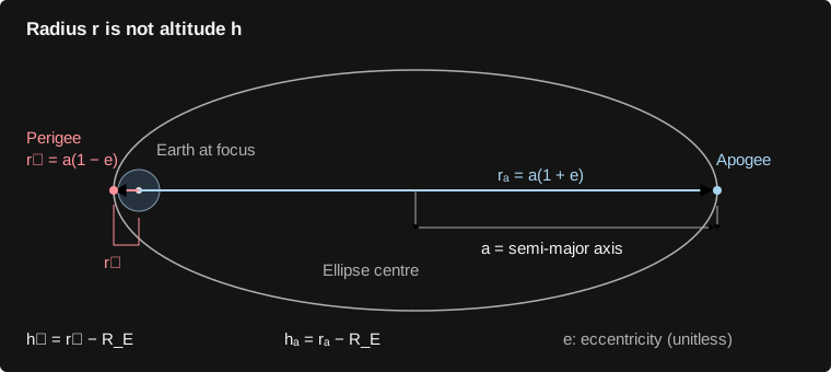
Compute perigee altitude from the cutoff state, using the same orbital quantities as before. The model requires a bound orbit, both apsides near the target, low radial speed, and low eccentricity together.
Perigee is the low point of the orbit implied by the current state.
The orbit must be bound and nearly circular.
Perigee must be within the altitude tolerance.
Apogee must independently be within the same tolerance.
A circular-speed crossing at the wrong altitude or with large radial motion is a failure.
Success also requires reaching the intended speed gate without impact. Failed insertion is reported as fuel depletion, missed orbit, impact, or timeout; it is never repaired by changing the state. A surviving failed insertion coasts for up to 1,200 s without release.
Scroll the diagram sideways to inspect both ends.
Associated code · 2 source excerpts
Copied directly from the implementation used by this site. Excerpts show the surrounding logic; run the complete downloaded notebook for dependencies and execution order.
def orbit_target_error(state, target_altitude_km):
    """Enter the target set only when BOTH apsides and radial speed agree.

    A proper target orbit is bound, within 2 km at each apsis, |vr| <= 5 m/s,
    and e <= 0.001. A negative result satisfies all four constraints.
    """
    orbit = orbital_elements(state)
    if orbit["apogee_km"] is None or orbit["specific_energy_j_kg"] >= 0:
        return 1e6
    return max(abs(orbit["perigee_km"] - target_altitude_km) / 2,
               abs(orbit["apogee_km"] - target_altitude_km) / 2,
               abs(state[2]) / 5, orbit["eccentricity"] / 0.001) - 1
            elements = orbital_elements(upper)
            reached = bool(cutoff_triggered and not upper_hit
                           and orbit_target_error(upper, target_altitude_km) <= 1e-8)
Coast ten seconds, then release the payload
Symbols in this section
- Payload-release and verified upper-stage cutoff times on the mission clock. [s]
- Combined mass immediately before release, retained upper-stage mass immediately after release, and payload mass. Superscript − means before the event, not negative mass. [kg]
- Common outward radial speed immediately before release, and retained-stage and payload radial speeds immediately after release. [m/s]
- Specified relative outward separation speed v_r,p − v_r,s = 0.2 m/s. It is the difference between the two final speeds, not the increment given to each body. [m/s]
After verified insertion at the upper-stage cutoff time , coast for ten seconds before release. Apply the same momentum-conserving separation rule, now with relative radial speed = 0.2 m/s. Let be payload mass and the retained upper-stage mass; is their combined mass just before release.
The deployment coast uses zero thrust; impact during this coast blocks release.
Only the retained body loses the payload mass; the total mass is conserved.
The retained upper stage receives the equal-and-opposite recoil.
The payload receives its share of the separation impulse. Position and tangential velocity are unchanged.
First finish the ten-second coast and accept its endpoint. At that same mission time, split the accepted mass and apply the equal-and-opposite velocity increments; then start one new integration per body. Reference area is 12 m² for the retained upper stage and 2 m² for the payload. The point masses begin at an identical location; the model assumes successful physical clearance.
Why these terms appear
Solve conservation of radial linear momentum together with the prescribed relative speed to obtain the two recoil formulas. This is an instantaneous internal impulse at a shared location. It conserves total momentum, but separation supplies a small amount of kinetic energy; no finite mechanism or contact force is modeled.
Associated code · 2 source excerpts
Copied directly from the implementation used by this site. Excerpts show the surrounding logic; run the complete downloaded notebook for dependencies and execution order.
            coast_name, duration = ("deployment_coast", 10) if reached else ("failed_insertion_coast", 1200)
            upper_time, upper, upper_hit, _ = phase("upper_stage", coast_name, upper,
                                                  upper_time, upper_time + duration, coast, body_area=12.0)
            if upper_hit:
                record("upper_impact", upper_time, "upper_stage", "Upper stage contacted the ground during unpowered flight.")
        if reached and not upper_hit:
            retained, payload = separate(upper, upper[4] - payload_kg, 0.2)
def separate(state, booster_mass_kg, relative_speed_m_s=0.5):
    """Split mass with equal/opposite impulses: conserve linear momentum.

    Both bodies start at the same position. Geometry and contact are not modeled.
    The reusable fairing stays within booster dry mass.
    """
    booster, upper = state.copy(), state.copy()
    upper[4] = state[4] - booster_mass_kg
    booster[4] = booster_mass_kg
    booster[2] -= relative_speed_m_s * upper[4] / state[4]
    upper[2] += relative_speed_m_s * booster[4] / state[4]
    return booster, upper
Propagate a whole unpowered revolution
Symbols in this section
- Earth gravitational parameter, 3.986004418 × 10¹⁴. [m³/s²]
- Payload specific energy and signed specific angular momentum immediately after release; the reference values for the drift tests. [J/kg; m²/s]
- Payload's osculating two-body semi-major axis and corresponding estimated orbital period. The subscript p denotes payload here, whereas denotes perigee. [m; s]
- Release time, requested integration endpoint, and actual endpoint returned by the solver, all on the mission clock. [s]
- Unwrapped Earth-centred angle, positive along the ascent direction, and its total change since release. The angle is not reset at 2π. [rad]
- Index of a returned solver state, and that state's mission time. These are accepted integration endpoints and the initial state, not the coarser playback frames. [integer index; s]
- Payload altitude r(t_n) − R_E at each checked state, and target altitude; the 2 km bound means 2,000 m. [m]
- Specific energy (v_r² + v_t²)/2 − μ/r and signed specific angular momentum r v_t evaluated at each checked state. [J/kg; m²/s]
- Largest value over all returned solver states. Relative drift divides by the nonzero release value, making it dimensionless. [operator]
Use the released payload's specific energy to estimate semi-major axis and orbital period . Then integrate for that duration; the estimated period does not substitute an analytic ellipse for the actual trajectory.
Evaluate payload energy from its post-release state, including the small separation impulse.
This is the requested unpowered propagation duration for both released bodies.
Propagate with zero thrust until requested time or ground contact. The actual endpoint must reach the requested time within 0.001 s, with no impact.
The swept angle is ; it must also cover a complete revolution within this angular tolerance.
Check every returned solver state, indexed by : the initial state, accepted step endpoints and any final event endpoint. All must remain near the target altitude and bound.
The maximum relative energy change over these solver states must remain small during the unpowered orbit.
The same relative bound applies to specific angular momentum, measured from its release value . These are discrete checks, not continuous extrema.
The period formula assumes an isolated bound two-body ellipse. The integrated coast retains the still-atmosphere drag model, so energy and angular momentum need only remain within the stated small drift thresholds, rather than being exactly conserved. Earth oblateness, Earth rotation, third bodies and orbital-plane dynamics are absent. The payload-orbit result comes from the integrated solution. This completes the upper branch. Next, return to separation and follow the booster on the shared mission clock.
Associated code · 2 source excerpts
Copied directly from the implementation used by this site. Excerpts show the surrounding logic; run the complete downloaded notebook for dependencies and execution order.
            energy = orbital_elements(payload)["specific_energy_j_kg"]
            semimajor_axis = -MU / (2 * energy)
            period = 2 * math.pi * math.sqrt(semimajor_axis**3 / MU)
            # Keep long-coast exports compact without changing solver steps.
            interval = max(sample_step_s, 10.0)
            phase("upper_stage", "post_release_coast", retained, upper_time, upper_time + period,
                  coast, body_area=12.0, sample_interval=interval)
            payload_time, _, _, solution = phase("payload", "free_flight", payload,
                upper_time, upper_time + period, coast, body_area=2.0, sample_interval=interval)
            payload_orbit = coast_verification(solution, period, target_altitude_km)
def coast_verification(solution, period_s, target_altitude_km):
    """Verify an actual propagated revolution; no analytic orbit is substituted."""
    radius, angle, vr, vt, _ = solution.y
    altitude_km = (radius - EARTH_RADIUS) / 1000
    energy = (vr**2 + vt**2) / 2 - MU / radius
    momentum = radius * vt
    energy_change = float(np.max(np.abs((energy - energy[0]) / energy[0])))
    momentum_change = float(np.max(np.abs((momentum - momentum[0]) / momentum[0])))
    duration = float(solution.t[-1] - solution.t[0])
    swept_angle = float(angle[-1] - angle[0])
    completed = abs(duration - period_s) < 1e-3 and not solution.t_events[0].size
    minimum, maximum = float(altitude_km.min()), float(altitude_km.max())
    initial_orbit = orbital_elements(solution.y[:, 0])
    success = (completed and np.all(energy < 0) and swept_angle >= 2 * math.pi - 1e-3
               and minimum >= target_altitude_km - 2 and maximum <= target_altitude_km + 2
               and energy_change < 1e-5 and momentum_change < 1e-5)
    return dict(success=bool(success), completed_one_orbit=bool(completed),
                period_s=period_s, propagated_duration_s=duration, swept_angle_rad=swept_angle,
                perigee_km=initial_orbit["perigee_km"], apogee_km=initial_orbit["apogee_km"],
                eccentricity=initial_orbit["eccentricity"],
                min_altitude_km=minimum, max_altitude_km=maximum,
                relative_energy_change=energy_change, relative_angular_momentum_change=momentum_change)
Booster branch
Booster → return and landing
Carry the booster state forward from the same separation epoch through closure, boostback, descent and feedback landing.
Coast while the upper stage clears the fairing
Symbols in this section
- Current mission time, shared stage separation, boostback ignition, and clearance-gated fairing closure times. [s]
- Prescribed fairing opening fraction: 1 means fully open and 0 fully closed. clip limits the result to this interval. [dimensionless]
- Outward radial and positive tangential engine forces; they are zero during the initial separation coast. [N]
- Booster mass including captive fairing and remaining recovery propellant, and its time derivative. [kg; kg/s]
Return to the booster state at stage separation, not the end of upper-stage flight. The booster retains its 90,000 kg mass, including 60,000 kg recovery propellant and the fairing. It coasts for four seconds before boostback. The fairing remains open until integrated upper-stage displacement along the release axis reaches 23.2 m, then closes over four seconds.
Boostback can start at , four seconds after separation.
The clearance root is found from the continuous integrated trajectories. Closure is kinematic: it neither ejects mass nor changes the aerodynamic reference area.
Advance the booster under gravity and drag with the established 7 m diameter reference area.
The branches are physically concurrent. Each starts from its own post-separation state at ; each force law advances its own state. The final fairing calculation compares both integrated positions at the same mission time. It does not feed back into either force law, even though Python evaluates one branch after the other.
Associated code · 3 source excerpts
Copied directly from the implementation used by this site. Excerpts show the surrounding logic; run the complete downloaded notebook for dependencies and execution order.
bt, booster, booster_hit, _ = phase("booster", "clearance_coast", booster, time, time + 4, coast)
    def fairing_fraction(time, body):
        opening = next((e["time_s"] for e in events if e["name"] == "fairing_opening"), None)
        if opening is None or body not in ("stack", "booster"):
            return 0.0
        if separation_time is None or time <= separation_time:
            return float(np.clip((time - opening) / 4, 0, 1))
        return float(np.clip(1 - (time - separation_time) / 4, 0, 1))
def apply_kinematic_hardware(trajectories, events, dense_phases):
    """Prescribed hardware coordinates, sampled from the actual integrated flight.

    Coast pointing uses a bounded cubic pre-alignment before the next ignition.
    Powered pointing is the actual force axis. Fairing closure waits for physical
    upper-stage clearance. No position, velocity, mass or applied force changes.
    """
    from scipy.optimize import brentq

    def phase_at(body, time):
        return next((phase for phase in reversed(dense_phases[body])
                     if phase["start"] <= time <= phase["stop"]), None)

    def state_xy(body, time):
        state = phase_at(body, time)["solution"].sol(time)
        return state[0] * np.array([math.cos(state[1]), math.sin(state[1])])

    def insert_samples(body, times):
        rows = trajectories[body]
        for time in times:
            if any(abs(row["time_s"] - time) < 1e-8 for row in rows):
                continue
            phase = phase_at(body, time)
            if phase is None:
                continue
            state = phase["solution"].sol(time)
            radius, angle, vr, vt, mass = map(float, state)
            force = phase["guidance"](time, state)
            thrust = float(np.linalg.norm(force))
            ca, sa = math.cos(angle), math.sin(angle)
            fx, fy = float(force[0] * ca - force[1] * sa), float(force[0] * sa + force[1] * ca)
            before = max((row for row in rows if row["time_s"] <= time), key=lambda row: row["time_s"])
            row = dict(before, time_s=float(time), phase=phase["name"],
                       altitude_m=radius - EARTH_RADIUS, downrange_m=EARTH_RADIUS * angle,
                       radial_velocity_m_s=vr, tangential_velocity_m_s=vt,
                       speed_m_s=math.hypot(vr, vt), mass_kg=mass, thrust_n=thrust,
                       force_x_n=fx, force_y_n=fy,
                       dynamic_pressure_pa=0.5 * atmosphere(radius - EARTH_RADIUS) * (vr * vr + vt * vt),
                       x_m=radius * ca, y_m=radius * sa,
                       vx_m_s=vr * ca - vt * sa, vy_m_s=vr * sa + vt * ca)
            if thrust > 0:
                row["axis_x"], row["axis_y"] = fx / thrust, fy / thrust
            if body == "booster" and any(sample.get("leg_open_fraction", 0) > 0 for sample in rows):
                command = next((event["time_s"] for event in events if event["name"] == "landing_burn"), math.inf)
                row["leg_open_fraction"] = float(np.clip((time - command) / 2, 0, 1))
            rows.append(row)
        rows.sort(key=lambda row: row["time_s"])

    for body, rows in trajectories.items():
        segments = []
        index = 0
        while index < len(rows):
            if rows[index]["thrust_n"] > 0:
                index += 1
                continue
            start = index
            while index < len(rows) and rows[index]["thrust_n"] == 0:
                index += 1
            if index == len(rows):
                break
            first, target = rows[start], rows[index]
            initial = math.atan2(first["axis_y"], first["axis_x"])
            final = math.atan2(target["force_y_n"], target["force_x_n"])
            turn = math.atan2(math.sin(final - initial), math.cos(final - initial))
            available = target["time_s"] - first["time_s"]
            duration = min(available, max(2.0, 1.5 * abs(turn) / COAST_POINTING_RATE_RAD_S))
            if duration > 0:
                segments.append((target["time_s"] - duration, target["time_s"], initial, turn))
        # Include the profile endpoints and 0.1 s kinematic samples even when
        # the caller chooses sparse trajectory output. States use RK45 dense
        # output here; they are never linearly invented or re-integrated.
        insert_samples(body, [float(t) for begin, end, _, _ in segments
                             for t in np.r_[np.arange(begin, end, 0.1), end]])
        for begin, end, initial, turn in segments:
            for row in rows:
                if row["thrust_n"] == 0 and begin <= row["time_s"] <= end:
                    u = float(np.clip((row["time_s"] - begin) / (end - begin), 0, 1))
                    angle = initial + turn * u * u * (3 - 2 * u)
                    row["axis_x"], row["axis_y"] = math.cos(angle), math.sin(angle)

    opening = next((event["time_s"] for event in events if event["name"] == "fairing_opening"), None)
    separation = next((event["time_s"] for event in events if event["name"] == "stage_separation"), None)
    if opening is None or separation is None or not trajectories["booster"] or not trajectories["upper_stage"]:
        return
    attached = trajectories["stack"][-1]
    axis = np.array([attached["axis_x"], attached["axis_y"]])
    def clearance(time):
        return float((state_xy("upper_stage", time) - state_xy("booster", time)) @ axis) - UPPER_EXIT_CLEARANCE_M
    stop = min(dense_phases[body][-1]["stop"] for body in ("booster", "upper_stage"))
    times = sorted(set(float(t) for body in ("booster", "upper_stage")
                       for phase in dense_phases[body] for t in phase["solution"].t
                       if separation <= t <= stop))
    close = math.inf
    for left, right in zip(times, times[1:]):
        if clearance(left) <= 0 <= clearance(right):
            close = float(brentq(clearance, left, right, xtol=1e-9))
            break
    events[:] = [event for event in events if event["name"] not in ("fairing_closing", "fairing_closed")]
    if math.isfinite(close):
        for name, time, text in [
            ("fairing_closing", close, "Captive fairing closes after integrated upper-stage clearance."),
            ("fairing_closed", close + 4, "Four-second closure completes after upper-stage clearance.")]:
            events.append(dict(name=name, time_s=time, body="booster", description=text,
                               required_axial_clearance_m=UPPER_EXIT_CLEARANCE_M))
        insert_samples("booster", [close, close + 4])
    for body in ("stack", "booster"):
        for row in trajectories[body]:
            time = row["time_s"]
            fraction = min(1.0, max(0.0, (time - opening) / 4))
            if time > close:
                fraction = max(0.0, 1 - (time - close) / 4)
            row["fairing_open_fraction"] = fraction
Reverse downrange motion, then cut off on predicted miss
Symbols in this section
- One engine's assumed available thrust, outward radial engine force, and signed tangential engine force. Negative F_t points against the positive downrange direction. [N]
- Vehicle geocentric radius, fixed Earth radius, and altitude h = r − R_E. [m]
- Earth gravitational parameter and current positive local gravity magnitude μ/r². The predictor holds this g constant during its imagined fall. [m³/s²; m/s²]
- Actual radial and tangential speeds at the predictor's starting state; v_r is negative while descending. [m/s]
- Nonnegative estimated time remaining until ground contact in the constant-gravity, drag-free predictor; it is a duration, not an absolute mission time. [s]
- Signed, unwrapped angle from the launch-site radius; positive toward the original ascent direction. [rad]
- Predicted signed miss at contact and actual current signed surface-arc distance x = R_E from the launch site. [m]
- Predicted miss crossing zero from positive to negative; this gate ends boostback. [event direction]
Assume three engines point directly against the positive tangential direction. Let be one engine's thrust, one ninth of the published nine-engine ascent thrust. For cutoff only, estimate remaining fall time under constant local gravity g and the current vertical state. The estimated ground miss is current downrange plus tangential speed times this fall time.
One engine's thrust is the nine-engine ascent thrust divided by nine.
Feed these forces into the same ODE with booster Isp = 330 s; this burn also consumes the recovery reserve.
The predictor assumes constant gravity and no drag. It only decides when to stop the burn.
Predicted miss is signed downrange distance from the launch site. This local approximation uses tangential speed as surface-distance rate; exactly, for . It also ignores curvature during the predicted fall.
Cut off at the downward zero crossing, or earlier at the dry-mass fuel floor or ground contact.
The actual path is still integrated with spherical gravity and drag; the predictor never overwrites position. This educational return-to-launch-site scenario differs from Rocket Lab's published downrange sea-recovery baseline. The boostback time limit is 300 s.
Why these terms appear
This constant-acceleration height equation is the predictor's model. The nonnegative root of this quadratic gives the stated fall-time expression; the main trajectory continues to use changing spherical gravity, drag and tangential motion.
Associated code · 2 source excerpts
Copied directly from the implementation used by this site. Excerpts show the surrounding logic; run the complete downloaded notebook for dependencies and execution order.
def predicted_miss(state, target_downrange_m=0.0, contact_height_m=0.0):
    """Cheap constant-g ballistic predictor used only to stop boostback.

    It does not set a landing position; the integrated trajectory can miss.
    Landing feedback subsequently corrects remaining position/velocity errors.
    """
    radius, angle, vr, vt, _ = state
    gravity = MU / radius**2
    fall_time = (vr + math.sqrt(vr * vr + 2 * gravity * max(0, radius - EARTH_RADIUS - contact_height_m))) / gravity
    return EARTH_RADIUS * angle + vt * fall_time - target_downrange_m
        engine = vehicle.booster_thrust_n / vehicle.booster_engines
        empty = terminal_event(lambda t, y: y[4] - vehicle.booster_dry_kg)
        initial_miss = predicted_miss(booster, recovery_target_downrange_m, contact_height)
        correction = -1.0 if initial_miss >= 0 else 1.0
        return_target = terminal_event(
            lambda t, y: predicted_miss(y, recovery_target_downrange_m, contact_height), correction)
        if not booster_hit:
            record("fairing_closed", bt, "booster", "Captive fairing closed for recovery.")
        if not booster_hit and booster[4] > vehicle.booster_dry_kg + 1e-3:
            record("boostback_ignition", bt, "booster",
                   "Three-engine range correction targets the fixed recovery ship." if ship_recovery
                   else "Three-engine boostback targets the launch site (assumed RTLS scenario).")
            bt, booster, booster_hit, solution = phase("booster", "boostback", booster, bt, bt + 300,
                                                       lambda t, y: np.array([0.0, correction * 3 * engine]), (empty, return_target))
            if not booster_hit:
                reason = "predicted zero miss" if solution.t_events[2].size else "propellant depletion" if solution.t_events[1].size else "time limit"
                record("boostback_cutoff", bt, "booster", "Boostback stops at " + reason + ".")
Coast to the landing-burn ignition point
Symbols in this section
- One engine's available thrust and current booster mass, including remaining recovery propellant. [N; kg]
- Earth gravitational parameter and current geocentric radius; μ/r² is the local gravitational acceleration magnitude. [m³/s²; m]
- Current altitude r − R_E and outward radial speed; only negative v_r contributes to the stopping-distance estimate. [m; m/s]
- Estimated upward net acceleration for three engines, floored at 1 m/s². This heuristic estimate is not a guaranteed available deceleration. [m/s²]
- Estimated vertical stopping distance at constant ; excludes tangential speed and lateral thrust demand. [m]
- The altitude-margin gate crossing zero from positive to negative; it triggers landing ignition. [event direction]
Coast with zero thrust after boostback. At each state, estimate maximum net upward acceleration from three engines, then compute stopping distance using only downward radial speed.
The acceleration estimate uses current mass and gravity, with a 1 m/s² lower bound.
Only descending speed contributes to this approximate stopping-distance gate.
Ignite at the downward crossing, leaving a 50% stopping-distance margin plus 3 km.
Descending through 80 km is recorded at 326.230 s; drag has acted continuously all along. This marker does not switch the atmosphere on. Ground impact remains terminal, and this coast is limited to 1,000 s.
Why these terms appear
The stopping-distance estimate is the familiar squared-speed relation for constant deceleration. Actual available vertical deceleration changes as fuel burns and thrust is redirected laterally; drag and polar geometry also act. The factor 1.5 and 3 km offset are chosen ignition margins, not guarantees of a safe touchdown.
Associated code · 2 source excerpts
Copied directly from the implementation used by this site. Excerpts show the surrounding logic; run the complete downloaded notebook for dependencies and execution order.
        def landing_gate(t, y):
            height, vr, mass = y[0] - EARTH_RADIUS - contact_height, y[2], y[4]
            maximum_deceleration = max(1.0, 3 * engine / mass - MU / y[0]**2)
            stopping_distance = min(vr, 0)**2 / (2 * maximum_deceleration)
            return height - 1.5 * stopping_distance - 3000
            gate = terminal_event(landing_gate)
            reentry = lambda t, y: y[0] - EARTH_RADIUS - 80_000
            reentry.direction = -1
            bt, booster, booster_hit, solution = phase("booster", "coast_and_reentry", booster, bt, bt + 1000,
                                                       coast, (gate, reentry))
Use the current descent error to command thrust
Symbols in this section
- Geocentric radius, fixed Earth radius, altitude r − R_E, and altitude clamped below at zero. [m]
- Actual outward radial speed, signed tangential speed, and desired radial descent speed. A negative radial value means descent. [m/s]
- Requested derivatives dot v_r and dot v_t. These are requests for changing the polar velocity components, not the physical acceleration projections before basis correction. [m/s²]
- Signed angle from launch and signed surface-arc downrange distance x = R_E ; x = 0 is the desired landing site. [rad; m]
- Estimated remaining landing duration, recomputed from the current state and bounded below by 3 s. [s]
- Current booster mass and Earth gravitational parameter. [kg; m³/s²]
- Signed drag-force components in the same radial/tangential frame. Subtracting these in the command compensates the drag already included in the ODE. [N]
- Engine-force components that would realize the requested velocity derivatives before any pointing or magnitude limits. A tilde denotes this unconstrained request. [N]
- Requested engine-force vector after setting any downward radial component to zero, and its Euclidean magnitude sqrt(,r² + ,t²). Bold symbols are vectors. [N]
- Single-engine available thrust, and final bounded engine-force vector [F_r, F_t] supplied to the dynamics. [N]
- Mass-consumption rate and fixed specific-impulse reference gravity (9.80665 m/s²); the assumed booster specific impulse is 330 s. [kg/s; m/s²]
First set a desired downward speed from height, clamped to . Then request radial acceleration to follow that speed. Use the estimated time remaining to drive both downrange and tangential speed toward zero.
This soft-descent profile approaches −1 m/s at ground level.
The first term follows the changing descent profile; the second corrects radial velocity error.
The time estimate stays finite near touchdown and during shallow descent.
The lateral request corrects position and tangential velocity. Using as is a near-surface approximation; the trajectory itself retains the exact polar equations.
Convert requested radial acceleration into engine force, compensating gravity, polar motion and drag.
Convert the tangential request into engine force with the matching polar and drag compensation.
Rectify the radial component so the engine cannot point downward; is this clipped vector.
is the magnitude of the rectified force vector, in newtons.
Scale to the assumed envelope from 30% of one engine to three full engines when N. Below that denominator guard, thrust can fall below the minimum; an exactly zero vector remains zero.
The update order at each RK45 trial state is: read current height, velocities and mass; construct the desired descent speed and landing-time estimate; request the two velocity derivatives; compensate gravity, basis rotation and drag; rectify the radial force; then limit total force. Feed only this final force into the ODE, with mass flow . The ODE produces actual derivatives and RK45 advances the state together. Rectification and magnitude limits can change both achieved derivatives, so the requested and must never be written straight into the state. Pointing and engine switching are ideal: ignition transients, attitude slew and gimbal limits are absent. The landing-burn time limit is 600 s.
Why these terms appear
Differentiate the desired speed with respect to height and use dot h = v_r. This gives the first, feed-forward term in . Adding ( − v_r)/(2 s) corrects tracking error. The chosen 6 m/s² shapes the descent-speed profile; it is not an additional force or the full engine acceleration.
Set the desired derivative dot v_t to and rearrange the actual ODE. This is why the command contains a positive v_r v_t/r compensation term: it cancels the negative moving-basis term in the velocity derivative. Tangential physical acceleration is (F_t + D_t)/m, not v_r v_t by itself.
Associated code · 1 source excerpt
Copied directly from the implementation used by this site. Excerpts show the surrounding logic; run the complete downloaded notebook for dependencies and execution order.
def landing_guidance(time, state, vehicle, target_downrange_m=0.0, contact_height_m=0.0):
    """Soft-descent velocity law + finite-time lateral position feedback.

    Ideal engine envelope: 0.3 of one engine to three engines. Engine switching,
    ignition transients, attitude slew and gimbal limits are not simulated.
    """
    radius, angle, vr, vt, mass = state
    height = max(0.0, radius - EARTH_RADIUS - contact_height_m)
    desired_vr = -math.sqrt(2 * 6.0 * height + 1.0**2)
    radial_request = -6.0 * vr / -desired_vr + (desired_vr - vr) / 2.0
    remaining = max(3.0, 2 * height / max(1.0, -vr))
    lateral_request = -6 * (EARTH_RADIUS * angle - target_downrange_m) / remaining**2 - 4 * vt / remaining
    acceleration = np.array([radial_request + MU / radius**2 - vt * vt / radius,
                             lateral_request + vr * vt / radius])
    area = math.pi * vehicle.diameter_m**2 / 4
    force = mass * acceleration - drag_force(state, area, vehicle.drag_coefficient)
    # Only upward pointing during the landing burn; bounded total force.
    force[0] = max(0.0, force[0])
    magnitude = np.linalg.norm(force)
    engine = vehicle.booster_thrust_n / vehicle.booster_engines
    return force * np.clip(magnitude, 0.3 * engine, 3 * engine) / max(magnitude, 1e-9)
Stop at contact and score what actually happened
Symbols in this section
- Integrated booster distance from Earth's centre and fixed spherical surface radius; contact occurs when they coincide. [m]
- Actual radial and tangential speeds at contact. Neither is reset when the landing is scored. [m/s]
- Signed angle from the launch-site radius at contact. [rad]
- Nonnegative total contact speed and absolute surface-arc distance from launch; both must satisfy their own limit. [m/s; m]
- Altitude crossing zero from positive to negative; this is a terminal impact/contact event. [event direction]
The downward ground crossing ends the flight. Evaluate impact speed and absolute downrange miss from that integrated state, then turn the engine display off. Do not force position or velocity to an ideal landing.
Ground contact is a solver-located event, not a sampled frame chosen by the renderer.
Both radial and tangential velocity contribute to contact speed.
Measure the actual surface-arc distance from the launch site.
Both tests must pass to label the contact a successful landing.
Every powered recovery phase has a downward mass gate at 30,000 kg booster dry mass. If fuel runs out, the remaining descent is unpowered for up to 1,000 s. Fast or remote contact is an impact; no contact before the phase limits is a recovery timeout. Contact mechanics and motion after impact are outside the model.
Associated code · 2 source excerpts
Copied directly from the implementation used by this site. Excerpts show the surrounding logic; run the complete downloaded notebook for dependencies and execution order.
        impact = terminal_event(lambda t, y: y[0] - EARTH_RADIUS)
        deck_events = ()
        if body == "booster" and ship_recovery:
            # A fixed flat deck, not an elevated spherical surface everywhere.
            # Check its finite along-track footprint at actual downward roots.
            def deck_crossing(t, y):
                return (y[0] * math.cos(y[1] - target_angle) - EARTH_RADIUS
                        - deck_height - leg_clearance * leg_fraction(t, body))
            deck_crossing.direction = -1
            deck_events = (deck_crossing,)
        solution = integrate(state, start, end, guidance, body_area, vehicle.drag_coefficient,
                             isp, (impact, *monitors, *deck_events), max_step_s, rtol)
        integrations += solution.nfev
        stop = float(solution.t[-1])
        hit = bool(solution.t_events[0].size)
        if hit and body == "booster":
            booster_contact_surface = "ocean" if ship_recovery else "ground"
        if deck_events:
            for contact_time in solution.t_events[-1]:
                contact_state = solution.sol(contact_time)
                along_track = contact_state[0] * math.sin(contact_state[1] - target_angle)
                if abs(along_track) <= RECOVERY_SHIP_LENGTH_M / 2:
                    stop, hit = float(contact_time), True
                    booster_contact_surface = "deck"
                    solution.t_events = [times[times <= stop + 1e-9] for times in solution.t_events]
                    break
        dense_phases[body].append({"start": float(start), "stop": stop,
                                   "solution": solution, "guidance": guidance, "name": name})
            speed = math.hypot(booster[2], booster[3])
            miss = abs(EARTH_RADIUS * booster[1] - recovery_target_downrange_m)
            success = (speed <= 2.0 and booster_contact_surface == "deck" and leg_fraction(bt, "booster") == 1
                       if ship_recovery else speed <= 2.0 and miss <= 100.0)
            contact = trajectories["booster"][-1]
            if contact["thrust_n"] > 0:
                record("booster_engine_cutoff", bt, "booster", "Engine shuts down at ground contact; contact mechanics are outside this model.")
            trajectories["booster"].append(dict(contact, phase="touchdown" if success else "impact",
                                                 thrust_n=0.0, force_x_n=0.0, force_y_n=0.0))
            landing = dict(success=bool(success), touchdown_time_s=bt, speed_m_s=speed,
                           miss_distance_m=miss, propellant_remaining_kg=max(0.0, booster[4] - vehicle.booster_dry_kg),
                           contact_surface=booster_contact_surface)
            record("touchdown" if success else "booster_impact", bt, "booster",
                   ("Soft landing on the fixed recovery deck." if ship_recovery else "Soft landing within 100 m of launch.")
                   if success else "Surface contact fails the speed or recovery-target criteria.")
Turn the state into the display
Symbols in this section
- Integrated geocentric radius and unwrapped angle. = 0 lies on the launch-site radius; increasing is the positive tangential direction. [m; rad]
- Cartesian position components in the fixed simulation plane, with Earth at the origin and launch on the positive X axis. These are physical positions before camera projection. [m]
- Requested playback mission time and the neighbouring distinct recorded mission times bracketing it, with t_a ≤ t ≤ t_b. [s]
- Interpolation fraction between those samples, from 0 at the earlier sample to 1 at the later sample. [dimensionless]
- Earlier recorded value, later recorded value, and displayed interpolated value of one numeric field, such as altitude or mass. z is a generic field, not a sixth physical state. [same units as the selected field]
The Run button calculates the entire mission in a Python worker before playback begins. The two physical branches are complete. To show them together on the shared mission clock, Python evaluates the dense numerical solution at output times. It records regular two-second samples and exact phase endpoints; the apogee coast and long post-release coasts use ten-second samples. Earth-centred drawing coordinates come directly from the integrated radius and angle.
These coordinates are derived for each recorded physical sample.
For a display time between adjacent recorded times , is the interpolation fraction.
For each numeric sample field , the browser interpolates the two neighbouring recorded values. The phase label stays with the earlier sample.
Playback speed scales elapsed wall time into display time; it does not change solver accuracy. Interpolated values never feed back into the physical state or event gates. At or beyond a body's last sample, the browser holds its final state. Complete mission success requires verified insertion, payload release, a verified propagated payload orbit, and successful booster landing together. These checks verify the assumed model's results; they do not validate real vehicle performance.
Associated code · 2 source excerpts
Copied directly from the implementation used by this site. Excerpts show the surrounding logic; run the complete downloaded notebook for dependencies and execution order.
    def phase(body, name, state, start, end, guidance, monitors=(), body_area=None, sample_interval=None):
        nonlocal integrations, booster_contact_surface
        body_area = area if body_area is None else body_area
        isp = vehicle.upper_isp_s if body in ("upper_stage", "payload") else vehicle.booster_isp_s
        impact = terminal_event(lambda t, y: y[0] - EARTH_RADIUS)
        deck_events = ()
        if body == "booster" and ship_recovery:
            # A fixed flat deck, not an elevated spherical surface everywhere.
            # Check its finite along-track footprint at actual downward roots.
            def deck_crossing(t, y):
                return (y[0] * math.cos(y[1] - target_angle) - EARTH_RADIUS
                        - deck_height - leg_clearance * leg_fraction(t, body))
            deck_crossing.direction = -1
            deck_events = (deck_crossing,)
        solution = integrate(state, start, end, guidance, body_area, vehicle.drag_coefficient,
                             isp, (impact, *monitors, *deck_events), max_step_s, rtol)
        integrations += solution.nfev
        stop = float(solution.t[-1])
        hit = bool(solution.t_events[0].size)
        if hit and body == "booster":
            booster_contact_surface = "ocean" if ship_recovery else "ground"
        if deck_events:
            for contact_time in solution.t_events[-1]:
                contact_state = solution.sol(contact_time)
                along_track = contact_state[0] * math.sin(contact_state[1] - target_angle)
                if abs(along_track) <= RECOVERY_SHIP_LENGTH_M / 2:
                    stop, hit = float(contact_time), True
                    booster_contact_surface = "deck"
                    solution.t_events = [times[times <= stop + 1e-9] for times in solution.t_events]
                    break
        dense_phases[body].append({"start": float(start), "stop": stop,
                                   "solution": solution, "guidance": guidance, "name": name})
        samples = np.unique(np.r_[start, np.arange(start, stop, sample_interval or sample_step_s), stop])
        for time, y in zip(samples, solution.sol(samples).T):
            radius, angle, vr, vt, mass = y
            force = guidance(time, y)
            cos_a, sin_a = math.cos(angle), math.sin(angle)
            speed = math.hypot(vr, vt)
            thrust = float(np.linalg.norm(force))
            force_x = float(force[0] * cos_a - force[1] * sin_a)
            force_y = float(force[0] * sin_a + force[1] * cos_a)
            if thrust > 0:
                pointing[body] = (force_x / thrust, force_y / thrust)
            trajectories[body].append(dict(
                time_s=float(time), phase=name, altitude_m=float(radius - EARTH_RADIUS),
                downrange_m=float(EARTH_RADIUS * angle), radial_velocity_m_s=float(vr),
                tangential_velocity_m_s=float(vt), speed_m_s=speed, mass_kg=float(mass),
                thrust_n=thrust, force_x_n=force_x, force_y_n=force_y,
                axis_x=pointing[body][0], axis_y=pointing[body][1],
                fairing_open_fraction=fairing_fraction(time, body),
                leg_open_fraction=leg_fraction(time, body),
                dynamic_pressure_pa=0.5 * atmosphere(radius - EARTH_RADIUS) * speed**2,
                x_m=radius * cos_a, y_m=radius * sin_a,
                vx_m_s=vr * cos_a - vt * sin_a, vy_m_s=vr * sin_a + vt * cos_a))
        final_state = solution.y[:, -1] if stop == float(solution.t[-1]) else solution.sol(stop)
        return stop, final_state.copy(), hit, solution
export function sampleAt(samples: FlightSample[], time: number) {
  if (!samples.length || time < samples[0].time_s) return null;
  let low = 0;
  let high = samples.length - 1;
  while (low < high) {
    const middle = Math.ceil((low + high) / 2);
    if (samples[middle].time_s <= time) low = middle;
    else high = middle - 1;
  }
  const first = samples[low];
  const next = samples[Math.min(low + 1, samples.length - 1)];
  const span = next.time_s - first.time_s;
  const fraction = span > 0 ? Math.min(1, (time - first.time_s) / span) : 0;
  const sample = { ...first };
  for (const key of Object.keys(first) as (keyof FlightSample)[]) {
    if (key !== 'phase')
      sample[key] = first[key] + fraction * (next[key] - first[key]);
  }
  return { sample, index: low, ended: time > samples.at(-1)!.time_s };
}
The complete calculated mission
Both branches are now complete. These results belong to the same 8,000 kg payload example followed above; each time is measured from launch.
A mission passes only when insertion, payload release, the full unpowered orbit check and booster landing all succeed.
- Upper-stage cutoff
- 3,270.846 s
- Insertion perigee
- 400.000 km
- Insertion apogee
- 400.000 km
- Payload release
- 3,280.846 s
- Verified unpowered orbit
- 5,553.624 s
- Booster touchdown
- 475.517 s
- Touchdown speed
- 1.272 m/s
- Landing miss
- 0.335 m
- Recovery propellant remaining
- 3,795.595 kg
Now run that flight below. Keep the payload at 8,000 kg to reproduce these values, then change it to see how the same equations respond.